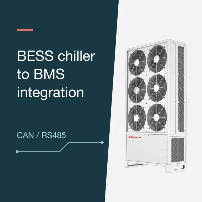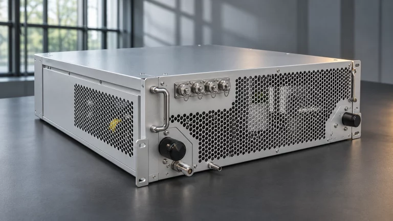

In the 215 kWh cabinet example below, a 6 kW chiller rated at 18 °C leaving coolant and 35 °C or 45 °C ambient air covers a calculated duty of 5.77 kW. Raising other heat on the same coolant loop from 0.40 kW to 1.00 kW lifts the duty to 6.43 kW, which takes that chiller off the shortlist with no change to the battery.
Cabinet data come from a public manufacturer datasheet and cell heat from a published laboratory measurement (see Sources). The two load cases are worked illustrations, not field measurements. The method works for any cabinet once you substitute its own cell heat data.
Four numbers a chiller quote must keep apart
A battery specification and a chiller quotation describe four different quantities.
- AC rated electrical output, 100 kW in this example, is the rated value at the cabinet AC output. Site losses and auxiliaries affect what reaches the grid connection.
- Battery energy, 215 kWh, is stored energy. It is an amount of energy, so it cannot be compared directly with a cooling rate.
- Chiller thermal capacity is the heat removed from the coolant, in kW, at a stated rating condition.
- Chiller electrical input is the power the chiller draws. Use the stated input for the auxiliary electrical budget. Check the rating boundary before accounting for heat transferred to the coolant by pumps or other auxiliaries.
The reference cabinet uses a 1P240S arrangement of 3.2 V, 280 Ah prismatic LFP cells. It has a 768 V nominal voltage, 215 kWh of energy and 100 kW of rated AC output. The energy figure checks out, because 240 × 3.2 V × 280 Ah = 215,040 Wh = 215.04 kWh. The datasheet lists a 0.5P power ratio, which is a different quantity from the 0.5C current used in the lab test below.
How much heat 240 cells put into the coolant
Lu et al. measured heat generation in a 280 Ah LFP cell during adiabatic charging. In a test starting at 15 °C, they report about 20.2 W per cell at 10% state of charge (SOC) during 0.5C charging. Lu et al., heat generation of a 280 Ah LFP cell (CUE2021)
The illustrative assumption here is that the cabinet charges at a constant current of 0.5C, which is 140 A for a 280 Ah cell. At the 768 V nominal voltage, that current corresponds to about 107.5 kW DC. That is above the cabinet’s 100 kW AC rating, so 0.5C is a stress case, not the cabinet’s confirmed charge current. The 20.2 W figure is one instant on one test cell. It is not a peak, and it was not measured on this cabinet’s cell. Scaling the single data point to 240 cells gives 20.2 W × 240 = 4.848 kW.
Where 6 kW passes and where it falls short
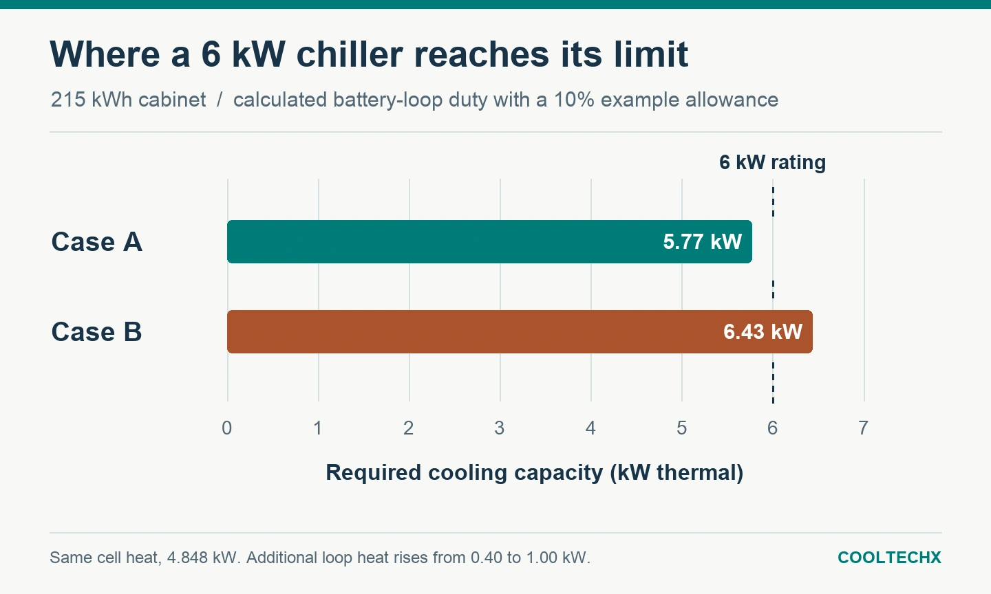
Both cases assume the full 4.848 kW is sustained and enters the battery coolant. Other net heat on the same loop is 0.40 kW in case A and 1.00 kW in case B. The 10% allowance is an example, not a recommended default. Pump and auxiliary heat are counted once, at the same boundary used for the chiller rating. Heat from a separately cooled PCS is excluded.
| Case | Calculation | Load | vs 6 kW |
|---|---|---|---|
| A | (4.848 + 0.40) × 1.10 | 5.77 kW | 0.23 kW margin |
| B | (4.848 + 1.00) × 1.10 | 6.43 kW | 0.43 kW short |
The comparison unit is the Cooltechx CTS0060W reference configuration. Cooltechx rates the unit at 6 kW of cooling at an 18 °C coolant supply temperature with ambient air at either 35 °C or 45 °C.
| Item | W18/L35 | W18/L45 |
|---|---|---|
| Cooling capacity | 6 kW | 6 kW |
| Cooling electrical input | 2.40 kW | 2.63 kW |
| Source | CTS0060W 6 kW liquid-cooled unit for energy storage | |
Case A passes only if the project runs at one of these rating conditions. Case B needs a larger unit or less other heat on the loop. Do not extrapolate these ratings to other supply temperatures, ambient temperatures or flows. Published W18/L45 ratings for other units in this capacity class, with their rating boundaries, are collected in the 5–6 kW BESS chiller specifications reference. The 15 °C figure in the lab test is the starting temperature of the cell. The 18 °C coolant supply belongs to a separate equipment rating. Confirm battery-to-coolant heat transfer at actual cell and coolant temperatures.
What to confirm before ordering
- Get a cell heat map from the cell supplier covering the actual duty cycle, C-rate, SOC window, temperature and state of health, including resistance growth with age.
- Use coolant properties at operating temperature. Glycol concentration changes heat capacity and viscosity, which affects both delivered capacity and pressure drop.
- The CTS0060W product page lists 50 L/min supply flow and 90 kPa customer-end resistance. Obtain the pump curve for the selected fluid and compare it with the cabinet pressure-drop curve to confirm the operating flow.
- Check branch restrictions. Cold plates, manifolds, quick couplings and filters set how flow divides between modules.
- Confirm whether pump heat sits inside or outside the rated capacity so that it is counted once.
- Compare site ambient extremes and the required supply temperature with the listed rating conditions.
The hydraulic checks are covered in more detail in the Cooltechx guide to BESS chiller flow rate and pressure drop.
Request a capacity check
- Cabinet model, cell chemistry, cell format and series-parallel arrangement
- Duty cycle as a C-rate or power profile, with cycles per day and SOC window
- Cell heat or internal resistance data versus temperature, SOC and age
- Required coolant supply temperature and allowed cell temperature spread
- Coolant type and concentration
- Required flow and the loop pressure drop at that flow
- Other heat sources on the loop, and whether the PCS has its own cooling
- Site ambient range, altitude and installation constraints
- Available power supply for the chiller
Send these inputs with a sizing request to get a candidate model checked at your design condition. Current units are listed in the Cooltechx C&I BESS liquid cooling range.
Sources
- Reference cabinet specification: manufacturer datasheet for a 215 kWh / 100 kW liquid-cooled C&I battery cabinet
- Cell heat: Lu et al., heat generation of a 280 Ah LFP cell, CUE2021
- Chiller ratings: Cooltechx CTS0060W product data