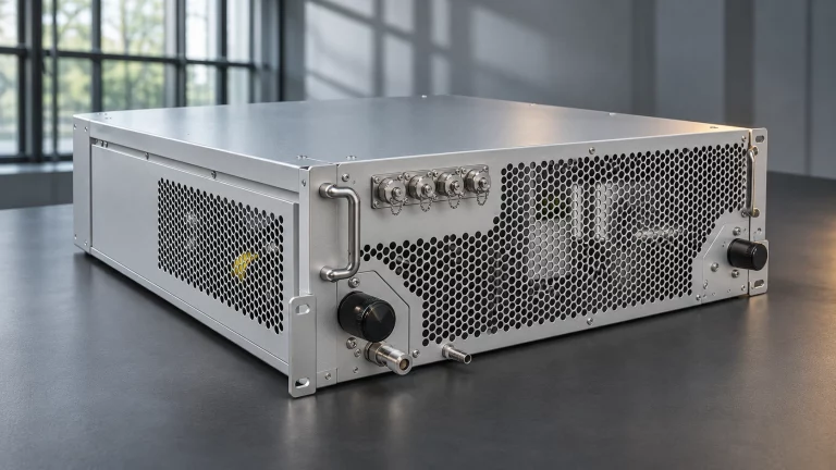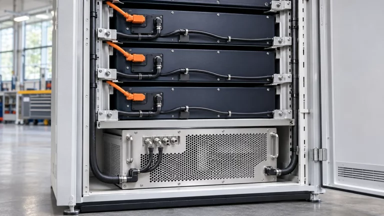

In a battery energy storage system, the liquid chiller can come from a different supplier than the BMS. The cooling unit has its own controller, and if the interface between the two is left until commissioning, integrators can find that the bus settings don’t match, a temperature reads ten times too high, or nobody decided what the chiller should do when the BMS stops talking.
This checklist covers what a BESS system integrator should agree with the chiller supplier before the unit ships: control authority, physical layer, protocol settings, data points, loss-of-communication behavior and site tests. We build the chillers, so we have written it from the chiller side of the interface.
Start with control authority
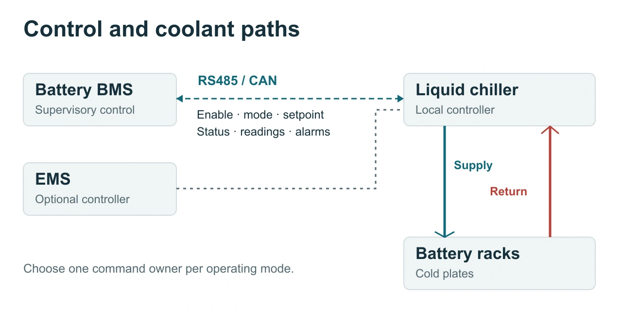
Before choosing a bus, decide which device makes which decision. Three arrangements are common:
- Monitoring only. The chiller regulates coolant temperature against its own local setpoint. The BMS or EMS reads status and alarms and uses them for derating and reporting.
- Supervisory control. The BMS writes a run command, an operating mode or a coolant setpoint. The chiller controller runs its own compressor, pump and heater loops to meet it.
- Through the EMS or site controller. The chiller talks to an EMS or local controller, which passes selected values to the BMS. This suits sites where several chillers report to one supervisory device.
We recommend keeping closed-loop temperature control inside the chiller and letting the BMS act at the supervisory level. The chiller controller has the refrigerant pressures, coolant temperatures and protection logic. The BMS has the cell temperatures and the charge and discharge plan. Splitting the work along that line keeps fast control loops off the serial bus, and the chiller can still protect itself if communication fails.
Write the choice down in the interface document. Every later item depends on it.
Communication interfaces on Cooltechx BESS cooling units
All our BESS liquid cooling units, including our containerized liquid cooling range, support both CAN and RS485.
RS485 or CAN?
Our BESS cooling units support both, so choose the bus your BMS or EMS already uses and that your site team can troubleshoot.
| RS485 (usually with Modbus RTU) | CAN | |
|---|---|---|
| Topology | Multi-drop, half-duplex, daisy-chained | Multi-drop bus, daisy-chained |
| Bus access | One master polls each slave in turn | Any node can transmit; the identifier sets priority |
| Data model | Registers read and written on request | Frames sent cyclically or on event |
| Addressing | One slave address per device | Message identifiers, 11-bit or 29-bit |
| Typical fit | EMS, PLC and SCADA integration; mixed-vendor sites | BMS platforms that already use CAN; fast cyclic data |
| Key project document | Register map | Message definition, often a DBC file |
RS485 with Modbus RTU is usually the easier choice when the master is an EMS, PLC or site controller, because most of those devices include a Modbus master driver. CAN suits BMS platforms that already exchange cyclic frames with racks and the PCS, provided both sides agree the message definitions in detail.
Modbus RTU settings to agree
The Modbus Organization specifications define the application protocol and the serial-line layer. The specifications leave several choices to the project. Agree each of these in writing:
- Slave address. Unicast addresses run from 1 to 247, and address 0 is broadcast. Give every chiller on a shared bus a unique address, and decide whether it is set on the controller or at the factory.
- Baud rate, parity and stop bits. The serial-line specification makes even parity the default and requires two stop bits when no parity is used. Some devices are configured differently, for example 9600 baud, 8 data bits, no parity and 1 stop bit, so confirm the actual setting on both sides.
- Function codes. Typical integrations use 03 (read holding registers), 04 (read input registers), 06 (write single register) and 16 (write multiple registers). Confirm which codes the chiller firmware accepts and which register ranges each one applies to.
- Address convention. Some documents call a register 40001 while others call the same register protocol address 0. State which convention the map uses so nobody reads every value one register off.
- Data types and scaling. Temperatures are often sent as signed 16-bit integers in 0.1 °C steps. Confirm signedness, scale factor and unit for every point, and word order for any 32-bit value.
- Polling and timeouts. Agree the polling interval, response timeout and retry count. Polling too fast on a shared bus can starve the other devices.
- Write persistence. Ask whether a written setpoint is held in RAM or saved to non-volatile memory. If the BMS rewrites a setpoint every few seconds and the controller saves each write, the memory can wear out early. The usual fix is to write only when the value changes.
CAN settings to agree
- Bit rate and sample point, matched on every node on the bus.
- Identifier format: standard 11-bit or extended 29-bit.
- Message definition: which frames each side sends, with identifiers, cycle times, byte order and signal scaling. A shared DBC file prevents most transcription errors.
- Heartbeat: how each side shows it is alive, for example a cyclic frame with a rolling counter, and how long the other side waits before it declares the link lost.
- Ownership of the definition: if your BMS already has a CAN protocol for auxiliary equipment, send it with your enquiry so we can check whether our chiller controller can be configured to match it.
Data points: a starting request list
Use the table below when you ask for the register map or message definition. It lists what integrators usually need. It is not a list of what our firmware provides on a given unit, so check each point against the project interface document.
| Category | Points to request | Direction |
|---|---|---|
| Status | Run or stop state; operating mode such as cooling, heating, circulation only or standby; compressor, pump and heater states | Chiller to BMS |
| Measurements | Coolant supply and return temperature, coolant pressure, ambient temperature | Chiller to BMS |
| Alarms | Alarm word or individual alarm bits with severity, plus a summary fault flag | Chiller to BMS |
| Commands | Remote run enable, mode request, coolant setpoint, alarm reset | BMS to chiller |
| Link health | Heartbeat or communication counter | Both directions |
For a dual-circuit unit that cools both the battery packs and the PCS, ask for status, measurements and alarms per circuit. The BMS can then tell a battery-side cooling fault from a PCS-side one.
Define loss-of-communication behavior
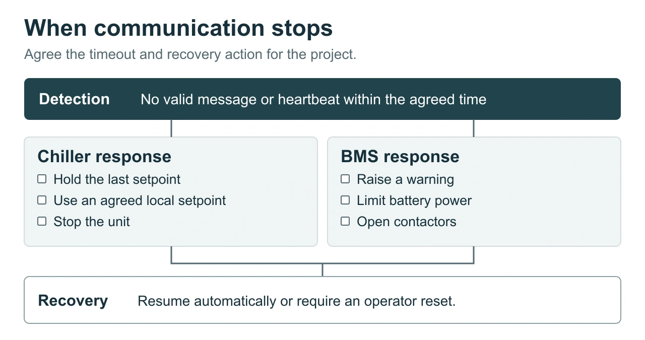
This behavior decides how the system reacts to a communication fault, so settle it before shipment. Agree four things:
- Detection. How long each side waits without a valid request or heartbeat before it declares the link lost.
- Chiller response. Whether the chiller keeps the last commanded setpoint, falls back to a local default setpoint, or stops. Take this response from the approved operating concept of the battery system, and state it in your enquiry. Do not rely on an unreviewed chiller default.
- BMS response. Whether the BMS raises a warning, limits charge and discharge power, or opens contactors when chiller data stops arriving, as defined in the same approved operating concept.
- Recovery. Whether control returns to the BMS automatically when the link comes back, or only after an operator reset.
Also define power-up behavior: what the chiller does before the BMS sends its first command. Then test all of it during commissioning, as described below.
Map chiller alarms to battery actions
A chiller alarm list means little to the BMS until each alarm is linked to an action. Sort the alarms into at least three groups and agree the BMS response for each:
- Information: logged and reported, with no change to battery operation.
- Warning: cooling capacity is reduced or at risk, and the BMS may derate.
- Fault: cooling is lost, and the BMS follows its thermal protection strategy.
Handle fire and emergency stop signals separately. Many projects use hardwired contacts for these instead of relying on a serial bus. Ask us which hardwired inputs and outputs the controller provides for your project, and record them in the same interface document.
Wiring practice for RS485 and CAN
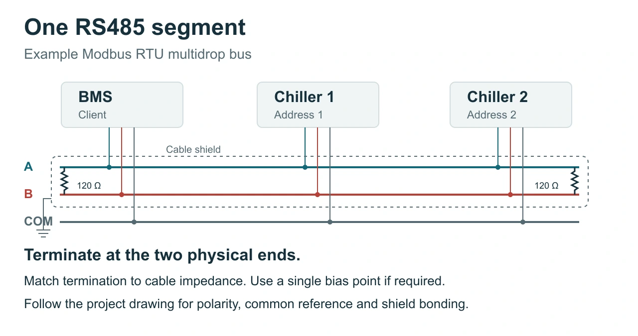
- Use shielded twisted-pair cable suitable for the bus, routed away from power and PCS cables.
- Daisy-chain the devices. Avoid star wiring and long stubs.
- Fit a termination resistor at each physical end of the bus and nowhere else, with a value matched to the characteristic impedance of the cable. For typical RS485 and CAN cable this is 120 Ω. Check whether the chiller controller has a built-in termination switch or jumper, and set it to match its position on the bus.
- On RS485, add line polarization (fail-safe biasing) only if the connected devices require it and do not already provide it. If it is needed, provide it at one location on the segment.
- Decide whether to run a common reference conductor, and how to connect and earth the shield, from the interface documentation of each device and the installation and earthing design for the site.
- Mark the bus ends and every device address on the wiring drawing.
Commissioning tests to run
Run these tests with the real BMS or EMS connected, not only a laptop simulator. Carry them out on an isolated test bench, or on site while the battery system is in an approved commissioning state under the commissioning procedure. Do not disconnect bus cables, power-cycle devices or trigger alarms on an energised system in normal operation. After handover, repeat a test only under the site’s permit-to-work and change procedures.
- Read every agreed point and compare it with the chiller’s local display or a calibrated reference. Scaling errors show up here.
- Send every command and confirm the chiller responds: run enable, mode change, setpoint change and alarm reset.
- Write an out-of-range setpoint and confirm the chiller rejects or limits it.
- Disconnect the bus cable and time link-loss detection on both sides. Confirm the agreed fallback behavior, then reconnect and confirm recovery.
- Power-cycle the chiller, then the BMS, and confirm each returns to the agreed state.
- Trigger or simulate representative alarms and confirm the BMS takes the mapped action.
- With every device on the bus active, run for an extended period and check timeout and error counts.
Record the results against the interface document. The record is useful at handover and again whenever firmware changes.
What to send with your enquiry
Integration goes faster when we see your side of the interface early. If you are planning a project with one of our BESS chillers, send us:
- Your BMS or EMS protocol document, or the register map or CAN definition you want the chiller to follow
- Your preferred bus, RS485 or CAN, and for RS485, the protocol (for example Modbus RTU) and which device is the master
- The number of chillers per bus and per container
- Your control philosophy: monitoring only, supervisory setpoints, or through the EMS
- The loss-of-communication and power-up behavior you require
- Heat load, coolant temperature range and site ambient conditions
Our engineers will review your documents against the controller configuration for the selected unit and tell you what can be matched. Use the enquiry form at the bottom right of this page.
Frequently asked questions
Can the chiller connect directly to the BMS without an EMS?
Yes, if the BMS has a free RS485 or CAN port and both sides use the agreed protocol. Whether the chiller reports to the BMS directly or through the EMS is a system architecture decision. Settle it before the interface document is written.
Can several chillers share one RS485 bus?
Yes, if the project uses Modbus RTU on RS485. Modbus RTU addresses each slave individually, so several chillers can share a segment if each has a unique address, the electrical load stays within the transceiver limits, and the full polling cycle still meets your update-time requirement.
Do Cooltechx BESS liquid cooling units include an Ethernet interface?
Ethernet is available as an option on our BESS liquid cooling units. Every unit comes with CAN and RS485 interfaces. If your project needs an Ethernet connection, mention it when you request a quote so we can confirm the configuration for your order.
Who provides the register map?
The register map or CAN message definition is agreed for each project. Ask us which interface documents are available for your chiller’s controller and firmware version, and send your BMS protocol if you want the chiller to follow it. Freeze the agreed version before factory acceptance testing, and put any later change under version control so the BMS configuration stays in step with the chiller firmware.