
A battery energy storage system (BESS) may advertise high battery efficiency and strong power conversion system (PCS) performance. But those figures do not always reflect how much electricity the entire storage plant consumes.
While batteries charge, discharge, or remain on standby, supporting equipment continues drawing power. Cooling systems, circulation pumps, control electronics, heaters, and safety equipment all contribute to BESS auxiliary power consumption.
Field data: auxiliary consumption in an operating BESS
A 2026 study of a 14.7 MW / 8.8 MWh BESS in Italy reported a median daily auxiliary-energy share of 4.5%, measured against the system’s total daily exchanged energy. Auxiliary power ranged from 8.5 to 72 kW, averaging 29 kW over the observation period. The air-cooled plant spent much of the observed period idle, so these site-specific results should not be treated as an industry-wide annual consumption benchmark. See Dimovski et al., Batteries (2026), Sections 3.1–3.3.
These loads may appear small compared with the system’s rated power, but their energy consumption accumulates over thousands of operating hours. Some continue consuming electricity even when the battery delivers no energy.
For investors, developers, EPC contractors, and system integrators, three questions matter:
- What counts as auxiliary power, and is it included in reported system efficiency?
- How much electricity does BESS thermal management consume under actual operating conditions?
- How does auxiliary consumption affect net energy delivery and the levelized cost of storage (LCOS)?
The answers require looking beyond equipment nameplates to whole-plant operating economics.
What Is the Parasitic Load in a Battery Energy Storage System?
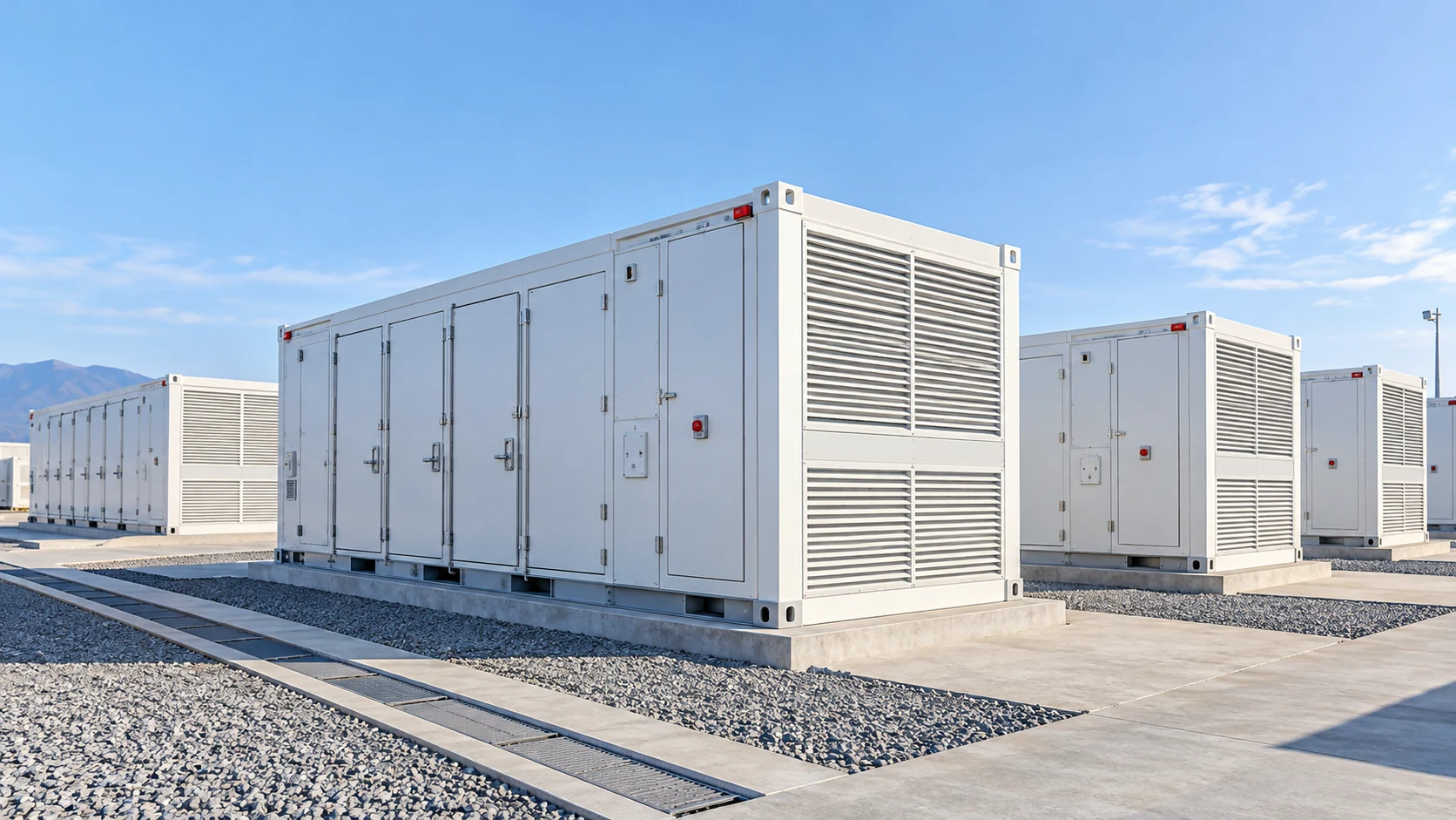
Auxiliary power, also called parasitic load, refers to electricity consumed by equipment that supports battery storage operation rather than directly supplying the intended energy output.
A battery energy storage auxiliary load typically includes several systems.
| Auxiliary system | Typical electrical loads | Main function |
|---|---|---|
| Thermal management | Compressors, fans, coolant pumps, heaters | Maintain battery operating temperatures |
| BMS and EMS | Controllers, monitoring equipment, communications | Manage battery and plant operation |
| Fire protection | Detection panels, monitoring circuits, suppression auxiliaries | Maintain safety readiness |
| Enclosure systems | Lighting, ventilation, HVAC, dehumidification | Maintain suitable enclosure conditions |
| PCS auxiliaries | Cooling fans, control electronics, internal supplies | Support power conversion |
| Transformer auxiliaries | Cooling fans, monitoring and control circuits | Support electrical infrastructure |
Not every project includes all these components. Some operate continuously, while others activate only under specific conditions.
For example, control electronics may remain powered around the clock, while compressors operate intermittently according to battery heat generation and ambient temperature.
There is also an important distinction between auxiliary power and auxiliary energy.
Auxiliary power is an instantaneous electrical demand, measured in kW. Auxiliary energy is the accumulated consumption over time, measured in kWh or MWh.
A cooling unit drawing 5 kW for two hours consumes 10 kWh. However, that does not mean it will consume 43,800 kWh annually. Actual consumption depends on how often it operates at that power level.
Definitions also vary between vendors and projects. One supplier may report only refrigeration-unit consumption, while another includes pumps and external fans.
Therefore, the measurement boundary must be defined before comparing auxiliary power figures.
Why It Stays Hidden: Metering Boundaries and Round-Trip Efficiency
BESS round-trip efficiency (RTE) measures how much energy a storage system returns compared with the energy supplied during charging.
The basic formula is:
RTE (%) = Discharged energy / Charged energy × 100
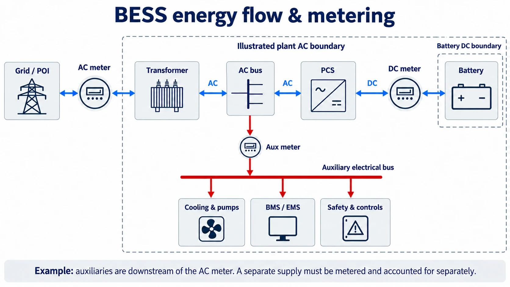
However, the location of the energy meters determines which losses are included.
DC-side vs. AC-side efficiency
DC-side RTE measures energy entering and leaving the battery at a defined DC boundary. It generally excludes losses associated with AC/DC conversion.
AC-side RTE measures energy at specified AC charging and discharging points, incorporating conversion losses between those boundaries.
But AC-side efficiency does not automatically include all auxiliary electricity.
For example, cooling equipment may be powered by a separate auxiliary supply that is not included in the meters used for the RTE calculation.
A quoted AC-to-AC efficiency figure therefore does not necessarily represent whole-plant net efficiency.
For example, Pacific Northwest National Laboratory’s Glacier BESS report lists one baseline test with RTE of 85.1% including auxiliary consumption and 87.6% excluding auxiliary consumption, a difference of 2.5 percentage points. This is a test-specific comparison of accounting boundaries, not a universal annual auxiliary-energy loss. See PNNL-28379, Table 2.1.
Why standby and idle consumption matter
A BESS parasitic load does not always scale with battery throughput.
Consider two storage plants with identical equipment but different operating schedules.
One cycles frequently, while the other spends long periods waiting for dispatch instructions.
Both may require continuous monitoring, periodic coolant circulation, and temperature control. The second plant can therefore have a higher ratio of auxiliary energy consumption to discharged energy, even if its absolute auxiliary consumption is lower.
This distinction matters when evaluating projects with different cycling patterns.
Contractual performance guarantees should clearly define the metering points, operating conditions, treatment of standby consumption, and included auxiliary equipment.
Before accepting a supplier’s efficiency figure, ask:
“At which meter was this efficiency figure measured, and does it include cooling and other auxiliary loads?”
Where the Energy Goes: Thermal Management Is Often the Largest Auxiliary Load
Thermal management is often one of the largest auxiliary electricity consumers in a battery storage system. In installations requiring substantial active cooling or heating, it may represent the largest individual auxiliary category.
Its actual contribution depends on climate, battery heat generation, operating schedules, and cooling-system architecture.
The main electrical consumers are:
- Compressors: Drive the refrigeration cycle and consume power according to cooling demand and operating conditions.
- Condenser fans: Reject heat from the refrigeration system to ambient air.
- Evaporator fans: Circulate conditioned air through air-cooled battery enclosures.
- Coolant pumps: Move coolant through liquid-cooled battery systems.
- Electric heaters: Maintain suitable operating temperatures during cold conditions.
These components do not necessarily operate simultaneously or at constant power.
Auxiliary consumption changes with operating state
| BESS operating state | Typical thermal-management behavior |
|---|---|
| Full-power charging or discharging | Higher battery heat generation may require increased cooling |
| Partial-load operation | Compressors, fans, and pumps may operate at reduced output |
| Standby or idle | Controls and circulation equipment may remain active while compressors stop |
| Extreme hot weather | Higher enclosure heat gains and more demanding heat rejection conditions |
| Cold weather | Heating or freeze-protection functions may become necessary |
For this reason, rated cooling-system power cannot be treated as continuous electrical demand.
A 30 kW electrical input at a specific full-load operating point does not mean the cooling system consumes 30 kWh every hour throughout the year.
Accurate BESS thermal management energy consumption estimates must account for the time spent in each operating state.
What Drives Auxiliary Consumption Up
Several factors influence how much electricity a BESS cooling system consumes.
1. Climate and ambient temperature
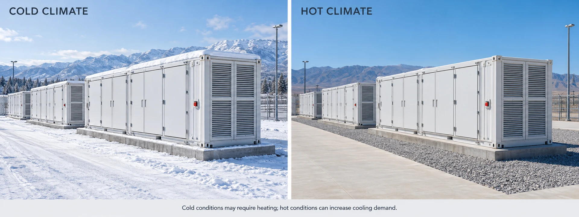
Higher ambient temperatures generally make heat rejection more difficult for mechanical refrigeration systems.
At a given cooling duty, higher condensing temperatures can increase compressor work and reduce efficiency.
Outdoor installations also experience solar radiation, humidity, dust, and variations in air density.
Direct sunlight increases enclosure heat gains. Dust buildup can restrict condenser airflow. High-altitude installations may experience reduced air-side heat-transfer performance.
Cold climates introduce a different challenge: electric heating may be needed to maintain battery temperatures within the required range.
2. C-rate and cycling pattern
Battery heat generation depends partly on charging and discharging current.
Higher C-rates can increase thermal loads, but annual consumption also depends on how long those conditions persist.
A project operating one short high-power cycle each day may have a different cooling profile from one delivering sustained output over several hours.
The annual charging and discharging schedule should therefore be considered alongside peak thermal load.
3. Temperature setpoints and cell uniformity
Lower temperature setpoints are not automatically more efficient or better for battery performance.
Unnecessarily aggressive cooling can increase compressor energy consumption.
At the same time, inadequate cooling distribution can create temperature differences between battery modules.
A suitable control strategy should maintain battery temperatures within the manufacturer’s specified operating limits while avoiding unnecessary refrigeration.
4. Enclosure design and control strategy
Insulation, shading, sealing, and airflow or coolant distribution affect the total cooling load.
Variable-speed compressors, staged operation, and appropriate temperature feedback can also reduce unnecessary equipment operation.
When supported by the system architecture, control based on battery temperature data can respond more directly to actual thermal requirements than a fixed enclosure-temperature setpoint.
From kWh to LCOS: A Worked Example
The commercial impact of auxiliary consumption becomes clearer when electrical power is converted into annual energy.
The basic calculation is:
Annual auxiliary energy = Sum of (auxiliary power in each operating state × hours in that state)
For example, a cooling-system energy estimate should account for cooling, circulation, standby, and heating operation where applicable.
These figures must use a consistent electrical measurement boundary.
Illustrative example: A 5 MWh BESS
Consider a hypothetical 5 MWh battery storage system operating one equivalent full cycle per day.
Assume the following:
| Parameter | Assumption |
|---|---|
| Reference energy per cycle | 5 MWh |
| Equivalent full cycles per year | 365 |
| Annual reference discharged energy | 1,825 MWh |
| Electricity value | USD 80/MWh |
| Analysis period | 15 years |
| Capacity degradation | Excluded |
| Discounting and electricity price escalation | Excluded |
The 1,825 MWh represents assumed annual discharged energy before the auxiliary-energy adjustment, not a measured plant output.
Now compare two hypothetical auxiliary-energy scenarios.
Scenario A: Lower auxiliary consumption
Assume total auxiliary energy equals 2% of annual reference throughput.
1,825 MWh × 2% = 36.5 MWh/year
Scenario B: Higher auxiliary consumption
Assume total auxiliary energy equals 5% of annual reference throughput.
1,825 MWh × 5% = 91.25 MWh/year
The annual difference is:
91.25 − 36.5 = 54.75 MWh/year
At an assumed electricity value of USD 80/MWh:
54.75 × 80 = USD 4,380/year
Over 15 years, without discounting:
4,380 × 15 = USD 65,700
What does this calculation mean?
The example shows how a difference in auxiliary electricity consumption can accumulate over a project’s operating life.
However, the 2% and 5% values are illustrative assumptions, not industry averages or measured product performance.
Likewise, USD 4,380 represents the hypothetical value of the energy difference. It is not necessarily the project’s additional profit or verified operating-cost savings.
The actual financial result depends on electricity tariffs, charging and discharging arrangements, auxiliary power supply, and the project’s commercial structure.
How auxiliary power affects LCOS
Levelized cost of storage evaluates the lifetime cost of delivering electricity from a storage system.
A simplified formula is:
LCOS = Discounted lifetime costs / Discounted lifetime discharged energy
For a net-energy calculation, the effective delivered energy may be expressed as:
Effective discharged energy = Reference discharged energy − Auxiliary energy converted to an equivalent output loss
This treatment applies only when the specified accounting boundary deducts auxiliary electricity from delivered energy.
If auxiliaries receive electricity through a separate grid supply, their cost may instead be accounted for in lifetime operating expenses. The same energy must not be counted twice.
The change between two scenarios can then be calculated as:
LCOS change = LCOS (Scenario B) − LCOS (Scenario A)
Actual LCOS requires project-specific assumptions about capital expenditure, operating costs, electricity prices, battery degradation, replacement costs, and discount rates.
The direct impact of auxiliary electricity on LCOS may be relatively modest in some projects. However, differences can become more consequential where operating conditions increase cooling demand.
Thermal management may also influence cell-temperature uniformity and battery aging, which can affect lifetime energy delivery. Those effects require separate battery-specific evidence and should not be treated as guaranteed savings.
Air Cooling vs. Liquid Cooling Through the Lens of Auxiliary Power
When comparing air-cooled and liquid-cooled BESS, the auxiliary-power question is not simply which technology has a higher nominal efficiency.
The relevant question is:
How much electrical energy does each complete thermal-management system require to maintain the specified battery temperatures under the same project conditions?
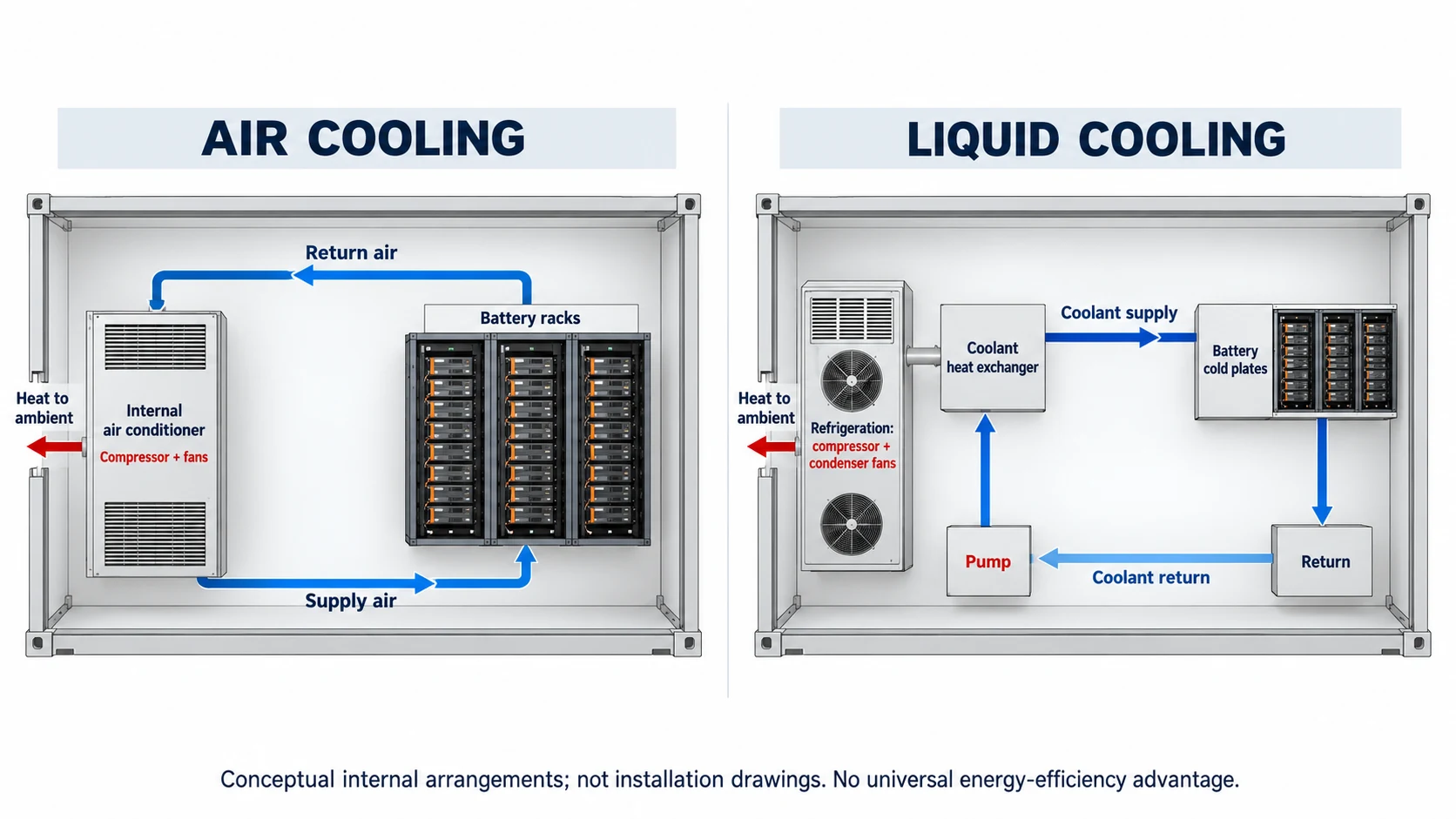
Air cooling uses fans to distribute conditioned air through the battery enclosure.
Liquid cooling transfers heat through a circulating coolant loop, introducing pump consumption alongside refrigeration-system electricity use.
Liquid cooling may provide effective heat transfer close to battery heat sources, but its circulation pumps require additional electrical power.
Air cooling avoids the battery coolant loop, although fan energy and air-distribution resistance can affect its overall consumption.
Heat-exchanger temperature differences and resulting compressor operating conditions also influence efficiency.
Neither method is automatically more energy efficient for every application.
For a broader equipment-selection comparison, see BESS Air Cooling vs. Liquid Cooling: How to Choose.
How ambient temperature changes cooling-system efficiency
Our laboratory test data below shows maximum cooling capacity, total input power, and COP for a 60 kW-class BESS liquid-cooling unit at an outlet coolant temperature of 18°C. “60 kW-class” refers to the unit’s cooling-capacity class at its rating condition of 45°C ambient temperature and 18°C outlet coolant temperature.
| Ambient temperature | Maximum cooling capacity | Total input power | COP | Input power per kW of cooling |
|---|---|---|---|---|
| 25°C | 85 kW | 26.24 kW | 3.24 | 0.31 kW/kW |
| 35°C | 76 kW | 31.7 kW | 2.40 | 0.42 kW/kW |
| 45°C | 61 kW | 33.0 kW | 1.85 | 0.54 kW/kW |
Source: Cooltechx laboratory test data; values are maximum-cooling operating points, not equal-load comparisons and not annual energy figures.
A separate laboratory test on a different unit at 45°C ambient temperature and 18°C outlet coolant temperature recorded a 60 kW cooling load, 31.5 kW electrical input, and COP of 1.9.
Between 25°C and 45°C, the electrical input needed per kW of cooling rises from about 0.31 to about 0.54 kW/kW, an increase of roughly 75% at these maximum-cooling operating points. This is why auxiliary energy must be estimated for the project’s own climate. These figures are not equal-load comparisons and do not give annual energy consumption.
For more on interpreting equipment ratings, read BESS Liquid Cooling Capacity: Why L45/W18°C Test Conditions Matter.
When evaluating annual energy consumption, buyers should request performance data across their expected climate and cooling-load range, not rely on a single rated COP.
Cooltechx offers BESS air cooling systems, utility-scale BESS liquid cooling units, and C&I BESS liquid cooling systems for different battery storage configurations.
How to Reduce Auxiliary Power: Design and Control Strategies
Reducing energy storage cooling power consumption requires an integrated approach to thermal design, equipment selection, controls, and maintenance.
Improve enclosure thermal design
Appropriate insulation, solar shading, and enclosure sealing can reduce unwanted heat gains.
Airflow channels and coolant distribution should also minimize local hot spots without requiring excessive fan or pump operation.
Select equipment for realistic operating conditions
Variable-speed compressors and fans can adjust output as cooling demand changes.
Equipment selection should consider part-load performance and expected operating hours, rather than rated cooling capacity alone.
Excessive capacity margins can lead to inefficient cycling, while insufficient capacity can compromise temperature control.
Optimize control logic
Where supported by the system design, battery-temperature feedback can help match cooling operation to actual thermal demand.
Staged compressor operation, suitable standby modes, and coordinated pump or fan control may reduce unnecessary energy consumption.
Control logic should also avoid simultaneous heating and cooling unless the system design specifically requires it.
Evaluate free-cooling opportunities
Free-cooling or refrigerant-pump-assisted approaches may reduce compressor runtime when outdoor conditions permit useful heat rejection without conventional mechanical refrigeration.
Their suitability depends on ambient temperature, required coolant or air temperatures, heat-transfer temperature differences, and the selected equipment configuration.
These functions are not universally suitable or available.
Maintain heat-transfer performance
Dirty condensers, blocked airflow paths, and neglected filters can reduce heat-transfer efficiency.
Regular maintenance helps preserve the equipment performance assumed during project design.
What to Ask Your Cooling Supplier: A Procurement Checklist
A cooling-system quotation should provide enough information to evaluate annual electrical consumption, not merely rated cooling capacity.
| Question | What to request |
|---|---|
| What is the rated COP or EER? | Cooling capacity, electrical input, and complete test conditions |
| How does efficiency change with load? | Part-load power and performance information |
| What is the standby power? | Measured standby and circulation-mode consumption |
| How does ambient temperature affect performance? | Cooling capacity and input power across the expected ambient range |
| Can annual energy be estimated? | A calculation based on project climate and operating profile |
| How were the results tested? | Test procedure, laboratory, applicable standard, and report identification |
| Can the controls integrate with the BMS? | Supported interfaces, available temperature feedback, and control responsibilities |
| Which loads are included in the quoted electrical input? | A clearly defined boundary covering compressors, fans, pumps, controls, and heaters where applicable |
Prepare the project’s location, battery thermal load, cycling schedule, and temperature limits before comparing quotations. See BESS cooling system selection inputs for the information to collect.
For related enclosure applications, review outdoor enclosure air conditioners.
RELATED SOLUTION
Planning a utility-scale BESS cooling system?
Explore Cooltechx’s Utility-Scale BESS Liquid Cooling Systems, then evaluate the configuration against your project’s climate, battery heat load, operating schedule, and temperature requirements.
To discuss a BESS cooling application, contact Cooltechx with your project inputs and request a preliminary technical assessment based on the available performance data. Any annual-energy estimate should state its assumptions, operating profile, and measurement boundary.
Conclusion: Evaluate BESS Auxiliary Power Consumption at the Plant Level
BESS auxiliary power consumption affects the electricity needed to operate a storage plant, including periods when the battery is not delivering energy.
Compare annual auxiliary energy under the same climate, battery thermal load, cycling schedule, and temperature requirements. Confirm whether the reported RTE includes those loads, and account for auxiliary electricity consistently in the LCOS model without double counting.
Neither nominal cooling capacity nor a single COP value provides a complete annual-energy comparison. Request operating-point data, standby consumption, and clearly defined test conditions before procurement.
Explore Cooltechx energy storage cooling systems as a starting point for matching thermal-management equipment to your project requirements.
Frequently Asked Questions
Does BESS round-trip efficiency include auxiliary power?
Not always. The answer depends on the metering boundary and contractual definition. DC-side efficiency may exclude PCS and auxiliary losses, while AC-side efficiency may still omit independently supplied cooling or supporting equipment. Before comparing RTE values, confirm the measurement points, included electrical loads, and operating conditions.
How much power does a BESS cooling system consume?
There is no universal value. Electrical consumption depends on battery heat generation, cooling capacity, ambient temperature, system efficiency, and operating state. Estimate annual consumption by multiplying the cooling system’s power demand in each operating state by the corresponding annual operating hours, then adding the results.
How does ambient temperature affect auxiliary consumption?
Higher ambient temperatures can increase cooling demand and make heat rejection more difficult, reducing refrigeration efficiency. Cold conditions may require battery heating, while mild conditions can permit reduced compressor operation. Actual annual consumption depends on local weather patterns, battery thermal load, temperature setpoints, and equipment controls.
Is liquid cooling always more energy efficient than air cooling?
No. Liquid cooling can provide effective heat transfer, but pumps consume electricity. Air cooling avoids coolant circulation while relying on fans and air distribution. The more efficient solution depends on total system power, required battery temperatures, heat load, climate, and operating profile—not the cooling method alone.
How can I estimate auxiliary power at the proposal stage?
Start with the project’s location, expected ambient-temperature distribution, battery thermal load, cycling schedule, and temperature requirements. Request cooling-system power data at relevant operating points, including standby and heating when applicable. Combine these figures with estimated annual operating hours and document the assumptions and metering boundaries.